Thursday, 31 May 2012

LOW COST PROGRAMMABLE LOGIC CONTROL (PLC) FOR INDUSTRIAL AUTOMATION IN REPETITIVE NATURE OF WORK


Model no.15: 

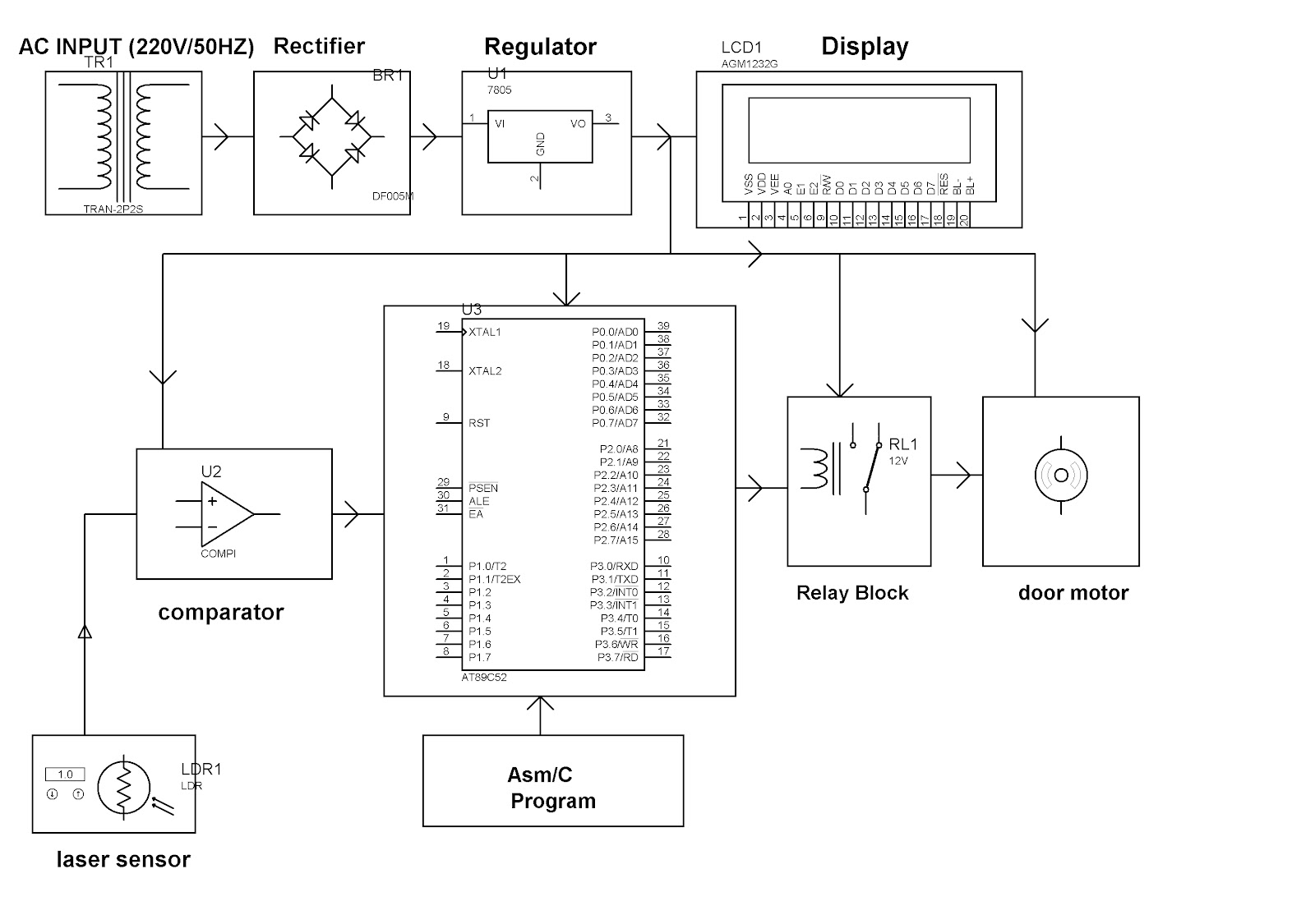
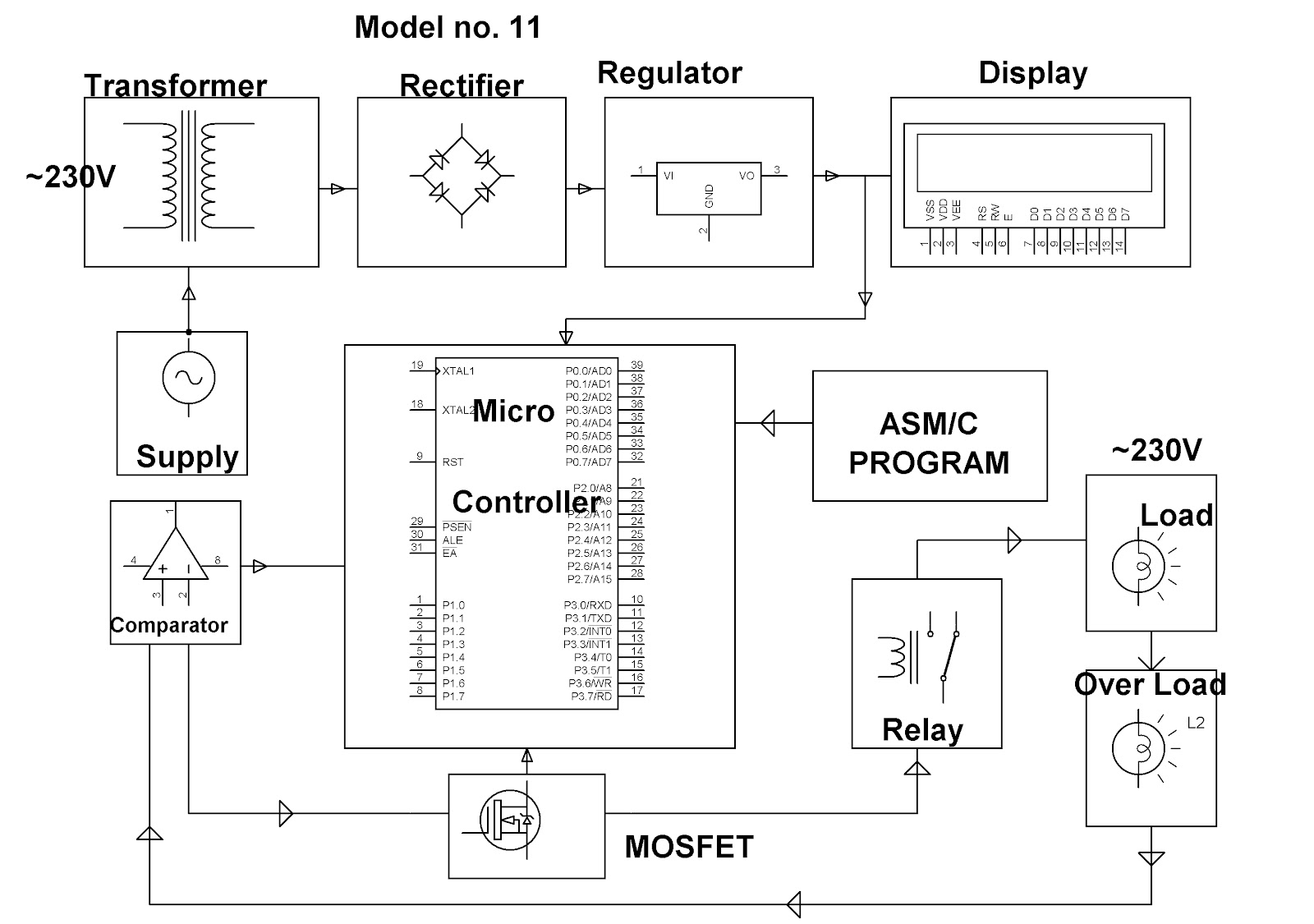
              The main objective of the project is designing a programmable sequential switching of any load using embedded system based microcontroller concept. It uses microcontroller from 8051 family which is of 8-bit. The development of this application requires the configuration of microcontroller architecture that is the selection of the machines, and writing debugging of the application program. In this project, the clock plays an important role, where it is used in the following mode i.e., the set mode, auto mode and manual mode for controlling different machines. In set mode, through the digital clock the machinery will run based on/off and on time where as in auto mode they will run by default settings and finally in the manual mode the real-time systems used extensively in industrial control applications can run depending on the user’s need and flexibility. The power supply consists of a step down transformer 230/12V, which steps down the voltage to 12V AC. This is converted to DC using a Bridge rectifier. The ripples are removed using a capacitive filter and it is then regulated to +5V using a voltage regulator 7805 which is required for the operation of the microcontroller and other components.

For more details about this project, please visit     http://www.efxkits.com/project-kit/microcontroller/1007.html


HARDWARE REQUIREMENTS:

Microcontroller unit, LCD (16x2), ULN2003, Relays, Resistors, Capacitors, LED, Crystal oscillator, Diodes, Transformer, Voltage Regulator, Push buttons, Loads.

SOFTWARE REQUIREMENTS:

Keil compiler, Language: Embedded C or Assembly.


Like us on Facebook.
Follow us on Twitter.
Visit our Website

Wednesday, 30 May 2012

TV REMOTE OPERATED CURTAIN CLOSER/OPENER


Model no. 14A:
     
            The main motto of the project is to operate the curtain raiser to open and close with a swing motor Wireless technology. In this project thesis, we are pressing a button from a TV remote which acts a transmitter and send signal to and it is received by IR receiver, the output signal from receiver is fed to a programmable microcontroller from 8051 family, is engaged to actuate the Swing Motor to rotate in forward and reverse direction indicating the curtain raiser open /close with help of relays which is driven by an IC ULN2003 (relay driver). The power supply consists of a step down transformer 230/12V, which steps down the voltage to 12V AC. This is converted to DC using a Bridge rectifier and it is then regulated to +5V using a voltage regulator 7805 which is required for the operation of the microcontroller and other components.

For more details about this project, please visit http://www.efxkits.com


HARDWARE REQUIREMENTS:

Microcontroller(AT89C52/S52), Crystal Oscillator, IR sensor, Relay Driver IC, Relays, Transformer, Diodes, 7805 voltage regulator, Capacitors, LED, Resistors, DC motor, TV Remote.

SOFTWARE REQUIREMENTS:

Keil Compiler, language: Embedded ‘C’ or Assembly.


Like us on Facebook.
Follow us on Twitter.
Visit our Website

BIDIRECTIONAL ROTATION OF AN EXHAUST FAN MOTOR WITH A REMOTE CONTROL DEVICE


Model no.14:

             The main motto of the project is to drive an Induction Motor for the required application in forward direction and reverse direction with Wireless technology.
In this project thesis, we are pressing a button from a TV remote which acts a transmitter and send signal to and it is received by a component called IR receiver, the output is fed to a programmable microcontroller from 8051 family, is engaged to actuate the Induction Motor to rotate in forward and reverse direction with help of relays which is driven by an IC ULN2003 (relay driver).
The power supply consists of a step down transformer 230/12V, which steps down the voltage to 12V AC. This is converted to DC using a Bridge rectifier and it is then regulated to +5V using a voltage regulator 7805 which is required for the operation of the microcontroller and other components.


For more details about this project, please visit http://www.efxkits.com/project-kit/microcontroller/1067.html


HARDWARE REQUIREMENTS:

Microcontroller(AT89C52/S52), Crystal Oscillator, IR sensor, Relay Driver IC, Relays, Transformer, Diodes, 7805 voltage regulator, Capacitors, LED, Resistors, Load, TV Remote.

SOFTWARE REQUIREMENTS:

Keil Compiler, language: Embedded ‘C’ or Assembly.


Like us on Facebook.
Follow us on Twitter.
Visit our Website

Tuesday, 29 May 2012

AUTOMATIC STAR DELTA STARTER USING RELAYS AND ADJUSTABLE ELECTRONIC TIMER FOR INDUCTION MOTOR


Model no.13:
                    Star/Delta starters are probably the most common reduced voltage starters in the 50Hz industrial motor world (Known as Wye / Delta starters in the 60Hz USA world). They are used in an attempt to reduce the start current applied to the motor during start as a means of reducing the disturbances and interference on the electrical supply. The Star/Delta starter is generally manufactured from three contactors; an electromechanical timer and a thermal overload for operating a 3 phase motor at 440 volt at ac mains supply 50 Hz. The interlocking arrangement of all the contactor coils is traditionally wired in 440 volt ac. However in our project we have taken up the same to operate a 3 phase motor at 440 volt ac mains supply 50 Hz with a set of 12 volt DC relays, an electronically adjustable timer and a set of miniature circuit breakers. The interlocking arrangement of the relay coils and the electronic timer are all wired in low voltage dc of 12 volt fed from an inbuilt dc power supply for safe handling of the starter during the study, still retaining its is application for a 3 phase motor starting with single phasing prevention .as the project would be expensive in using a 3 phase induction motor the project shall be tested with a set of lamps for each phase. During star operation the lamps would glow dim indicating the supply voltage across the coils are 440/sqrt (3) and while in delta condition after the timer operates the lamps would glow with full intensity indicating full supply voltage of 440volts. The timer comprises of a 555 in mono-stable mode the output of which is fed to a relay for changing the mains supply from 3 phase star to delta. The project also has the provision of single phasing protection since 3 phase motors get burnt if any one phase goes missing during running. The output to the lamps shall be completely cut-off in the event of any phase failure.


Like us on Facebook.
Follow us on Twitter.
Visit our Website

LASER BEAM CONTROLLED GARAGE DOOR OPENER


Model no.12A:
           This project is designed to operate a garage door remotely by laser beam. The circuit comprises of a laser beam sensor built using op-amp IC LM358. Op-amp’s are configured here as a comparator. The Microcontroller used is 8-bit, 40 pin from 8051 family. It is used to control the whole system by monitoring the sensors and when the laser sensor receives the signals then the microcontroller will send command to relay driver IC the contacts of which are used to switch on the motor used for opening the garage door and it will switch off the motor after predetermined time. The status of the door whether it is open or closed is displayed on the 16X2 LCD interfaced with the microcontroller. The power supply consists of a step down transformer 230/12V, which steps down the voltage to 12V AC. This is converted to DC using a Bridge rectifier. The ripples are removed using a capacitive filter and it is then regulated to +5V using a voltage regulator 7805 which is required for the operation of the microcontroller and other components.


For more details about this project, please visit http://www.efxkits.com/project-kit/microcontroller/1066.html


HARDWARE REQUIREMENTS:

Microcontroller unit, LM358, LCD(16x2), Relay, garage door, LDR, Voltage Regulator, Diodes, Capacitors, Resistors, LED, Crystal oscillator, BC547.

SOFTWARE REQUIREMENTS:

Keil compiler, Languages: Embedded C
And or Assembly


Like us on Facebook.
Follow us on Twitter.
Visit our Website

AUTOMATIC IRRIGATION SYSTEM ON SENSING SOIL MOISTURE CONTENT


Model no.12:
         
             In the field of agriculture, use of proper method of irrigation is important because the main reason is the lack of rains & scarcity of land reservoir water. The continuous extraction of water from earth is reducing the water level due to which lot of land is coming slowly in the zones of un-irrigated land. Another very important reason of this is due to unplanned use of water due to which a significant amount of water goes waste. For this purpose; we use this automatic plant irrigation system. The circuit comprises of sensor parts built using op-amp IC LM358. Op-amp’s are configured here as a comparator. Two stiff copper wires are inserted in the soil to sense whether the soil is wet or dry. The Microcontroller is used to control the whole system by monitoring the sensors and when sensors sense the dry condition then the microcontroller will send command to relay driver IC the contacts of which are used to switch on the motor and it will switch off the motor when all the sensors are in wet condition. The microcontroller does the above job as it receives the signal from the sensors through the output of the comparator, and these signals operate under the control of software which is stored in ROM of the Microcontroller. The condition of the pump i.e., ON/OFF is displayed on a 16X2 LCD. This is safest and no manpower is required. This is very useful to all climatic conditions and it is economic friendly. The power supply consists of a step down transformer 230/12V, which steps down the voltage to 12V AC. This is converted to DC using a Bridge rectifier. The ripples are removed using a capacitive filter and it is then regulated to +5V using a voltage regulator 7805 which is required for the operation of the microcontroller and other components.

For more details about this project, please visit      http://www.efxkits.com/project-kit/microcontroller/1006.html


HARDWARE REQUIREMENTS:

Microcontroller unit, LM358, LCD(16x2), Relay, Water Pump, Voltage Regulator, Diodes, Capacitors, Resistors, LED, Crystal oscillator, BC547.

SOFTWARE REQUIREMENTS:

Keil compiler, Languages: Embedded C
And or Assembly


Like us on Facebook.
Follow us on Twitter.
Visit our Website

ULTRA FAST ACTING ELECTRONIC CIRCUIT BREAKER FOR A 3 PHASE INDUCTION MOTOR


   ULTRA FAST ACTING ELECTRONIC CIRCUIT BREAKER FOR A 3 PHASE INDUCTION MOTOR


Model no.11B:
           
           The outline of the project is to shut down the power supply when it is overloaded. Conventional circuit breaker is based on thermal bimetal lever trip mechanism, which is very slow and the trip time is dependant upon the percentage of overload. So, Electronic circuit breaker is designed which is based on the voltage drop across a series element typically a low value resistor or a CT (current Transformer). The voltage sensed is compared against the preset voltage proportional to the current by a level comparator to generate an output for the 3 Contact relay (or contactor , optionally) to trip the 3 phase load in the event of overload, over voltage and single phasing . The unit is extremely fast and overcomes the drawback of the thermal type. It uses an 8-bit microcontroller from 8051 family into which program is burnt for the operation of this project. The power supply consists of a step down transformer 230/12V, which steps down the voltage to 12V AC. This is converted to DC using a Bridge rectifier. The ripples are removed using a capacitive filter and it is then regulated to +5V using a voltage regulator 7805 which is required for the operation of the entire circuit ,microcontroller and other components.


.

HARDWARE REQUIREMENTS:

Microcontroller unit, Op-amp,
Transformer, MOSFET, Diodes, Capacitors, Resistors, LED, Crystal Oscillator, LCD (16x2), Voltage Regulator, 3 CO Relay, 3 Ph IM

SOFTWARE REQUIREMENTS:

Keil compiler, Languages: Embedded C
or Assembly


Like us on Facebook.
Follow us on Twitter.
Visit our Website.

ULTRA FAST ACTING ELECTRONIC CIRCUIT BREAKER


Model no.11:

             The outline of the project is to shut down the power supply when it is overloaded. Conventional circuit breaker is based on thermal bimetal lever trip mechanism, which is very slow and the trip time is dependant upon the percentage of overload. So, Electronic circuit breaker is designed which is based on the voltage drop across a series element typically a low value resistor or a CT (current Transformer). The voltage sensed is compared against the preset voltage proportional to the current by a level comparator to generate an output for the Relay or contactor to trip the load. The unit is extremely fast and overcomes the drawback of the thermal type. It uses an 8-bit microcontroller from 8051 family into which program is burned for the operation of this project. The power supply consists of a step down transformer 230/12V, which steps down the voltage to 12V AC. This is converted to DC using a Bridge rectifier. The ripples are removed using a capacitive filter and it is then regulated to +5V using a voltage regulator 7805 which is required for the operation of the microcontroller and other components.


For more details about this project, please visit   http://www.efxkits.com/project-kit/microcontroller/1005.html


HARDWARE REQUIREMENTS:

Microcontroller unit, Op-amp,
Transformer, MOSFET, Diodes, Capacitors, Resistors, LED, Crystal Oscillator, LCD (16x2), Voltage Regulator, Relay, Lamps.

SOFTWARE REQUIREMENTS:

Keil compiler, Languages:
Embedded C or Assembly


Like us on Facebook.
Follow us on Twitter.
Visit our Website.

Friday, 25 May 2012

INDUSTRIAL BATTERY CHARGER WITH HIGH POWER DC BY THYRISTOR FIRING ANGLE CONTROL


Model no.10:

             The outline of the project is DC battery power control by microcontroller. The zero crossing point is detected by zero crossing detector and fed to the microcontroller. The microcontroller fires the thyristor by using the opto isolator. The power is applied to the load through a thyristor to the bridge rectifier. The rectified and controlled output is given to the DC load. The output is measured using a multimeter. This project uses a microcontroller from 8051 family. The power supply consists of a step down transformer 230/12V, which steps down the voltage to 12V AC. This is converted to DC using a Bridge rectifier. The ripples are removed using a capacitive filter and it is then regulated to +5V using a voltage regulator 7805 which is required for the operation of the microcontroller and other components.

For more details about this project, please visit    http://www.efxkits.com/project-kit/electrical/1119.html


HARDWARE REQUIREMENTS:

Microcontroller unit, Op-amp, Opto-isolator, Thyristor, Voltage Regulator, Transformer, Diodes, Crystal oscillator, LED, Push button, Resistors, Capacitor, Load.

SOFTWARE REQUIREMENTS:

Keil compiler, Language: Embedded C or Assembly


Like us on Facebook.
Follow us on Twitter.
Visit our Website.

DISPLAY TURN TABLE SPEED CONTROL FOR SHOPS


                                       DISPLAY TURN TABLE SPEED CONTROL FOR SHOPS


Model no.9A:

           The outline of the project is Cycle stealing, as a method to remove whole cycle, cycles or portions of cycles of an AC signal, is a well-known and old method of controlling AC power, especially across AC heater loads. However the concept of achieving the cycle stealing of voltage waveform by use of microcontroller can be very precise as per the program written in assembly/ C language. So that the actual time-average voltage or current experienced at the load is proportionately lower than if the whole signal is to be applied to the load. The load to be operated shall be a single phase synchronous motor for speed and direction control. In this project we are using comparator for zero crossing detectors as an interrupt to microcontroller. Here the microcontroller gives the output on the base of interrupt as the reference for generating the firing control. Using the output we drive the opto-isolator which acts as switching element using this we will trigger the TRIAC on the base of TRIAC we can make the cycle stealing. On the base of cycle stealing we can control the speed of swing motor. The power supply consists of a step down transformer 230/12V, which steps down the voltage to 12V AC. This is converted to DC using a Bridge rectifier. The ripples are removed using a capacitive filter and it is then regulated to +5V using a voltage regulator 7805 which is required for the operation of the microcontroller and other components

For more details about this project, please visit     http://www.efxkits.com/project-kit/electrical/1151.html


HARDWARE REQUIREMENTS:

Microcontroller unit, Op-amp, Opto-isolator
TRIAC, Resistors, Capacitors, Diodes, Voltage
Regulator, LED, crystal oscillator, LCD (16x2), load

SOFTWARE REQUIREMENTS:

Keil compiler, Language: Embedded C
Or Assembly


Like us
 on Facebook.
Follow us on Twitter.
Visit our Website.

INDUSTRIAL FURNACE POWER CONTROL BY INTEGRAL CYCLE SWITCHING WITHOUT GENERATING HARMONICS


Model no.9:

            The outline of the project is integral Cycle switching, as a method to remove whole cycle, cycles or portions of cycles of an AC signal, is a well-known and old method of controlling AC power, especially across AC heater loads. However the concept of achieving the cycle stealing of voltage waveform by use of microcontroller can be very precise as per the program written in assembly/ C language. So that the actual time-average voltage or current experienced at the load is proportionately lower than if the whole signal is to be applied to the load. The load to be operated shall be a single phase series motor for speed control or a lamp. One side effect of utilizing this scheme is an imbalance in the input current or voltage waveform as the cycles are switched on and off across the load. In this project we are using comparator for zero crossing detectors as an interrupt to microcontroller. Here the microcontroller gives the output on the base of interrupt as the reference for generating the firing control. Using the output we drive the opto-isolator which acts as switching element using this we will trigger the TRIAC on the base of TRIAC we can make the cycle stealing. The power supply consists of a step down transformer 230/12V, which steps down the voltage to 12V AC. This is converted to DC using a Bridge rectifier. The ripples are removed using a capacitive filter and it is then regulated to +5V using a voltage regulator 7805 which is required for the operation of the microcontroller and other components

For more details about this project, please visit     http://www.efxkits.com/project-kit/microcontroller/1004.html


HARDWARE REQUIREMENTS:

Microcontroller unit, Op-amp, Opto-isolator
TRIAC, Resistors, Capacitors, Diodes, Voltage
Regulator, LED, crystal oscillator, LCD (16x2), load

SOFTWARE REQUIREMENTS:

Keil compiler, Language: Embedded C
Or Assembly


Like us on Facebook.
Follow us on Twitter.
Visit our Website.

SUPER FAST SOLID STATE RELAY SWITCHING ON TIME ANALYSIS ON CRO


Model no.8:

             The project is taken up for a three phase solid state relay that incorporates three single phase units. Each phase is controlled individually by a power TRIAC with optional snubber network (RS, CS) and an optically isolated TRIAC driver with current limit by a constant current arrangement. All LED’s are connected in series and can be controlled by one logic gate or controller. One microcontroller is used to generate output pulses after zero voltage pulse to verify as to whether the load is getting the switched on at zero cross of the supply wave form or not. The zero crossing feature of the TRIAC driver, (an opto-isolator) ensures lower generated noise avoiding sudden inrush currents on resistive loads and moderate inductive loads. Here in this project we are using two push buttons which are used as up down buttons which are used for increasing the speed of the AC motor. This buttons are given to microcontroller as inputs. On the base of input signal from push button the MOC3063 is used as a switching element this is the opto-isolator is zero crossing switching element. On the base of this switching element TRIAC will be triggered.


For more details about this project, please visit     http://www.efxkits.com/project-kit/electrical/1117.html


HARDWARE REQUIREMENTS:

Microcontroller (AT89C52/S52), Opto Isolator, SCRS, Transformers, Diodes, voltage regulator, push button, LED, Resistors, Capacitors, Crystal oscillator, Load.

SOFTWARE REQUIREMENTS:

Keil compiler, Languages: Embedded C or Assembly


Like us on Facebook.
Follow us on Twitter.
Visit our Website.


Thursday, 24 May 2012

RANDOM ON/OFF OF LAMPS TO DETECT BURGLARS FOR LOCKED HOUSES


Model no.7A:

            Random ON/OFF time in periodical intervals is generated by the programmed microcontroller which is fed to a pair of opto isolators to trigger the TRIAC used in series with the load. The lamp load thus switches ON and OFF randomly through the night indicating a situation of somebody’s presence in the house to detect burglars. As frequent ON/OFF of the lamp might reduce the life of the same, we have incorporated a Zero Voltage Switching such that the lamp always switches on at the zero cross of the supply waveform. The project is having comparator which is used for ZVS output. The ZVS (ZERO VOLTAGE START) is given as reference interrupt to microcontroller. The microcontroller is of 8051 family which is of 8bit. In this we are using push button as switch which is used as reference interrupt to microcontroller and using that interrupt we give signal to opto-isolator. The opto-isolator used in the project is used as switching element using this we will trigger the TRIAC. On the base of TRIAC triggering the AC lamp can be controlled to ON at low voltage. This will increase the life of the lamp. The power supply consists of a step down transformer 230/12V, which steps down the voltage to 12V AC. This is converted to DC using a Bridge rectifier. The ripples are removed using a capacitive filter and it is then regulated to +5V using a voltage regulator 7805 which is required for the operation of the microcontroller and other components.

For more details about this project, please visit   http://www.efxkits.com/project-kit/microcontroller/1065.html


HARDWARE REQUIREMENTS:

Microcontroller (AT89C52/S52), LM358, Opto Isolators, TRIAC, Transformer, Diodes, voltage regulator, push button, LED, Resistors, Capacitors, Crystal oscillator, lamp.

SOFTWARE REQUIREMENTS:

Keil compiler, Languages: Embedded C or Assembly


Like us
 on Facebook.
Follow us on Twitter.
Visit our Website.


OVERHEAD PROJECTOR LAMP LIFE EXTENDER BY ZVS (ZERO VOLTAGE SWITCHING)


Model no.7:

             Incandescent lamps exhibit very low resistance in cold condition. Thus at the time of switching from cold state it draws very high current. Thus many lamps fail at the time of switch ON. Engaging two SCR’s in anti parallel or a TRIAC the switching ON time can be precisely controlled by firing after detecting the zero cross point of the waveform of supply voltage. This should result in current waveform rising from zero at the time of switching ON there by increasing the life of lamp. The project is having comparator which is used for ZVS output. The ZVS (ZERO VOLTAGE START) is given as reference interrupt to microcontroller. The microcontroller is of 8051 family which is of 8bit. In this we are using push button as switch which is used as reference interrupt to microcontroller and using that interrupt we give signal to opto-isolator. The opto-isolator used in the project is used as switching element using this we will trigger the back to back SCR. On the base of SCR triggering the AC lamp can be controlled to ON at low voltage. The power supply consists of a step down transformer 230/12V, which steps down the voltage to 12V AC. This is converted to DC using a Bridge rectifier. The ripples are removed using a capacitive filter and it is then regulated to +5V using a voltage regulator 7805 which is required for the operation of the microcontroller and other components.

For more details about this project, please visit    http://www.efxkits.com/project-kit/electrical/1116.html


HARDWARE REQUIREMENTS:

Microcontroller (AT89C52/S52), LM358, Opto Isolators, TRIAC, Transformer, Diodes, voltage regulator, push button, LED, Resistors, Capacitors, Crystal oscillator, Load.

SOFTWARE REQUIREMENTS:

Keil compiler, Languages: Embedded C or Assembly


Like us on Facebook.
Follow us on Twitter.
Visit our Website.

HIGH POWER AC LAMP FLASHER FOR AVAITION OBSTRUCTION INDICATION PURPOSE


Model no.6A:

             The project is based on the principle of firing angle delay of thyristors using back to back SCR’s in series with the load with control being fed from a microcontroller via opto isolators. The firing angle would be adjusted to maintain the load power by rising and decreasing slowly the intensity of the lamp load, resembling the situation of a flasher for aviation obstruction light used in tall buildings. The above operation can also be carried out by using a TRIAC in series with the load.
The project is having comparator which is used for ZVR output. The ZVR is given as reference interrupt to microcontroller. The microcontroller is of 8051 family which is of 8bit. In this we are using switch which is used for increasing the firing angle. The opto-isolator used in the project is used as switching element using this we will trigger the back to back SCR. On the base of SCR triggering the intensity of the AC lamp can be controlled.
The power supply consists of a step down transformer 230/12V, which steps down the voltage to 12V AC. This is converted to DC using a Bridge rectifier. The ripples are removed using a capacitive filter and it is then regulated to +5V using a voltage regulator 7805 which is required for the operation of the microcontroller and other components.


For more details about this project, please visit     http://www.efxkits.com/project-kit/electrical/1149.html


HARDWARE REQUIREMENTS:

Microcontroller (AT89C52/S52), LM358, Opto Isolators, SCRS, Push Button, Transformer, Diodes, voltage regulator, Resistors, Capacitors, Crystal oscillator, Load.

SOFTWARE REQUIREMENTS:

Keil compiler, Languages: Embedded C or Assembly


Like us
 on Facebook.
Follow us on Twitter.
Visit our Website.


A LOW COST MICRO CONTROLLER BASED SYSTEM HIGH PERFORMANCE AC MOTOR DRIVES


Model no.6:

            The project is based on the principle of firing angle delay of thyristors using back to back SCR’s with control being fed from a microcontroller via opto isolators. The firing angle would be adjusted to maintain the load power by an up and down switch. The above operation can also be carried out by using a TRIAC in series with the load.
The project is having comparator which is used for ZVR output. The ZVR is given as reference interrupt to microcontroller. The microcontroller is of 8051 family which is of 8bit. In this we are using switch which is used for increasing the firing angle. The opto-isolator used in the project is used as switching element using this we will trigger the back to back SCR. On the base of SCR triggering the intensity of the AC lamp can be controlled.
The power supply consists of a step down transformer 230/12V, which steps down the voltage to 12V AC. This is converted to DC using a Bridge rectifier. The ripples are removed using a capacitive filter and it is then regulated to +5V using a voltage regulator 7805 which is required for the operation of the microcontroller and other components.


For more details about this project, please visit    http://www.efxkits.com/project-kit/electrical/1115.html


HARDWARE REQUIREMENTS:

Microcontroller (AT89C52/S52), LM358, Opto Isolators, SCRS, Push Button, Transformer, Diodes, voltage regulator, Resistors, Capacitors, Crystal oscillator, Load.

SOFTWARE REQUIREMENTS:

Keil compiler, Languages: Embedded C or Assembly


Like us
 on Facebook.
Follow us on Twitter.
Visit our Website.


Wednesday, 23 May 2012

MIXER GRINDER SPEED CONTROL BY USING A TV REMOTE

     
The main scope of project is to control the mixer grinder speed by using IR remote. A standard TV remote is used with IR sensors connected to a microcontroller which reads the coded data from the remote for each button pressed to activate the corresponding output pin. This changes the time delay for the thyristor firing angle in 8 steps that drives the mixer grinder. Also the firing angle is displayed on a 7-segment LED display. The microcontroller does the above job as it receives the signals from the sensors, and these signals operate under the control of software, which is stored in ROM. All the above systems are controlled by the microcontroller. In this project we are using 8-bit, 40 pin microcontroller. A lamp load shall be provided in case motor is not taken. The power supply consists of a step down transformer 230/12V, which steps down the voltage to 12V AC. This is converted to DC using a Bridge rectifier. The ripples are removed using a capacitive filter and it is then regulated to +5V using a voltage regulator 7805 which is required for the operation of the microcontroller and other components.


For more details about this project, please visit       http://www.efxkits.com/project-kit/microcontroller/1003.html


HARDWARE REQUIREMENTS:

OP-Amp, TRIAC or 2 SCRs in anti parallel, Opto-isolator (MOC3021), Resistors, Capacitors, Diodes, LED, Transformer, Voltage Regulator, Microcontroller unit, TSOP (IR sensor), Seven segment display.

SOFTWARE REQUIREMENTS:

Keil compiler, Languages: Embedded C or Assembly


Like us on Facebook.
Follow us on Twitter.
Visit our Website.